
As part of a bulk purchase of Atari related items I had done, was an Atari 1050 Disk Drive. Of course, with any vintage hardware one might acquire, it is good practice to inspect such devices before applying power to said device. In my inspection of the Atari 1050 disk drive, there was a distinct rattling sound of which I knew was not a feature of this device in its original configuration. So, it was time to pull out my screwdriver and open it up to see what all this noise was about.
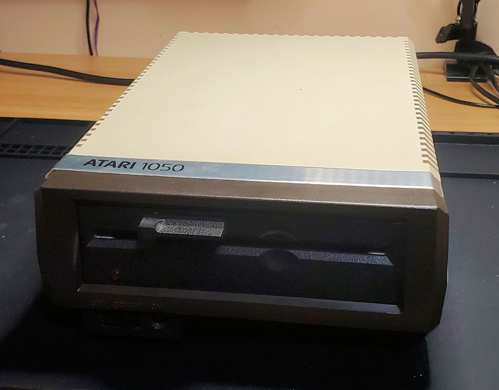
For those who don’t know, (which might include some of my family members) the Atari 1050 disk drive is a 5.25-inch floppy disk drive manufactured by Atari in the 1980’s. It is used for data storage on the Atari 8-bit computers.
Upon removing the screws and removing the top of the case, it became clear that the rattling noise I heard came from a capacitor bouncing about loose inside the unit. This is not the normal way a capacitor works so it’s clear I have some repair work to do before we get to power this unit up just to see if there are any other issues to be addressed.
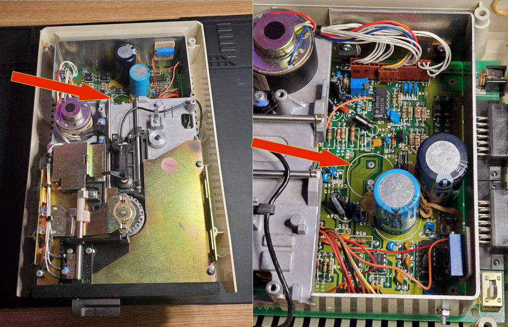
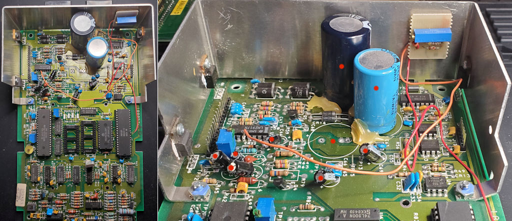
The arrows above point to the spot where a capacitor should be. Also, if you look closely at the view on the right you can see what looks to be the remains of a rubber-band. And furthermore, it almost looks like someone attempted to put some glue or epoxy between the missing capacitor and the light blue capacitor just in front of it. I’m really not sure what was trying to be accomplished here, but whatever it was looks to be an epic fail in my opinion. You can also see a hardware modification which we will get to in a bit.
The Capacitor
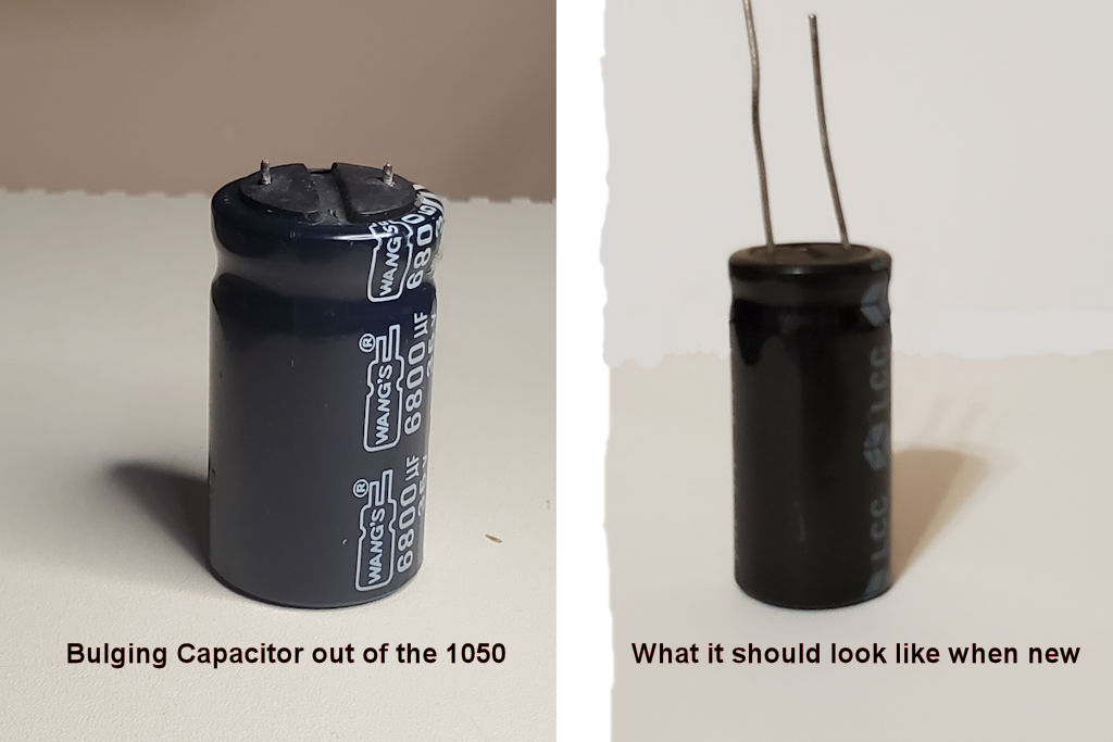
Okay, this is a first for me, I’ve seen leaking capacitors, and even bulging capacitors, but this is the first time I’ve found a bulging capacitor from the bottom in such a way that it literally popped the capacitor out of its socket. Admittedly the solder joints for the capacitor are forty years old but I still found it interesting to see. What this means is that I will replace all the electrolytic capacitors in this disk drive before we power it up.
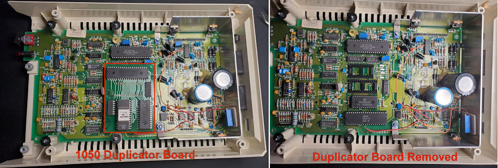
As I alluded to previously, during the inspection of the unit I clearly saw a modification that had been made to this unit. This 1050 was modified with the 1050 Duplicator from Duplicating Technologies Inc. As best I understand, this upgrade worked much like the Happy Computer enhancement that allowed for creating backups from copy protected disks. However, based on what documentation I’ve found thus far, the 1050 Duplicator attempted to remove the copy protection and make your backup disks non-protected which would allow you to simply copy the non-protected disks as often as you like and would work with any disk drive. Clearly this did not make the developers of such copy protected software happy. It also provided via the hardware, faster read/write speeds and double density disk capabilities.
If I were to guess, those blobs next to the big capacitors is hot-gun glue. Could it be they wanted to make the capacitors more secure on the board? Still don’t know what the rubber-band is all about.
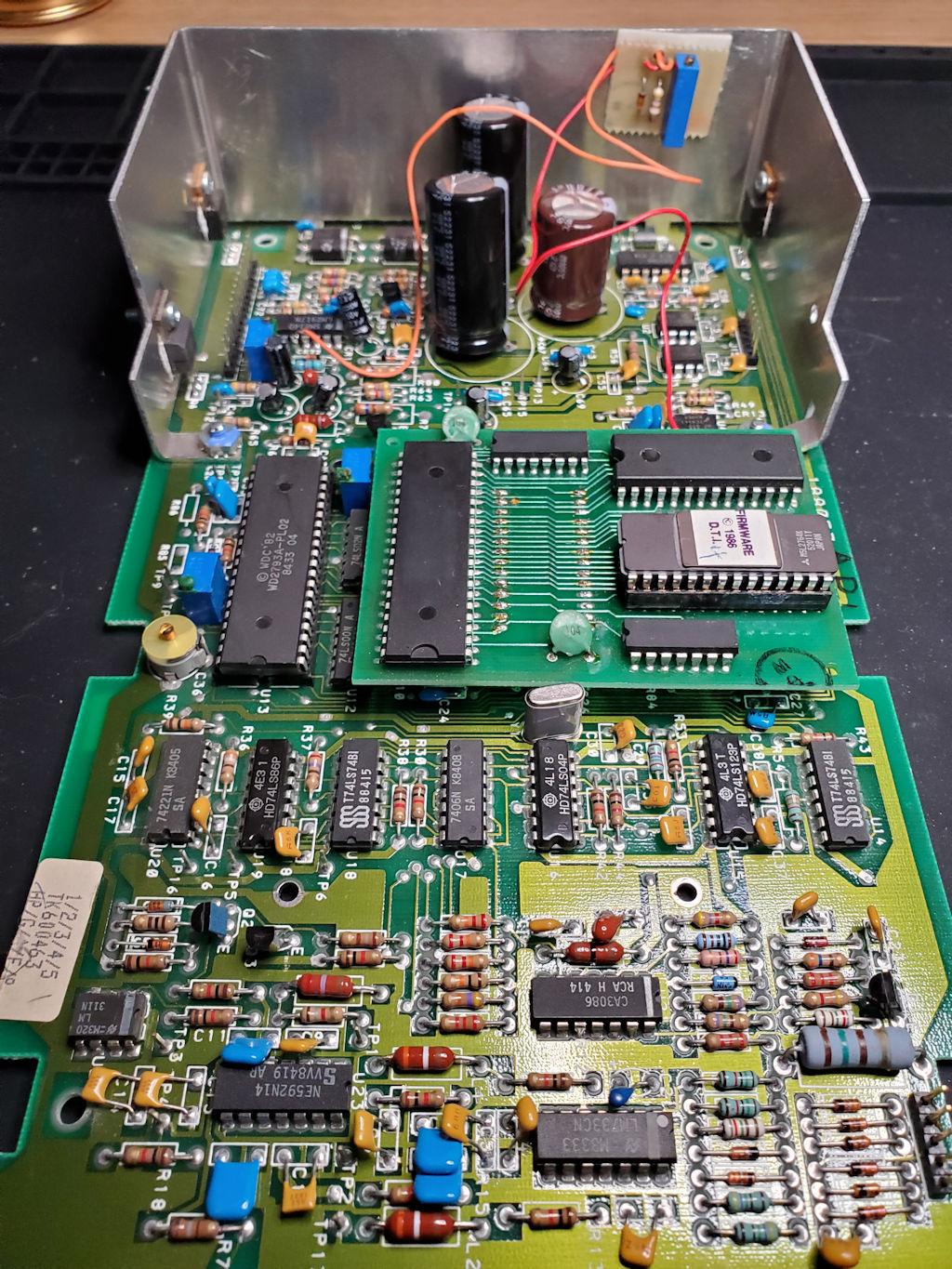
Back to my thoughts on the 1050 Duplicator. Attached to the large aluminum heatsink there is a small board with a blue component. I am guessing that this is some sort of Cermet Trimmer resistor as it does have an adjustment screw. The board is attached by double sided tape which has long since dried out and this board will easily fall out of place. So, as I confirmed the falling out of place bit, I did see there are a couple other components on the board under that tape. And as the picture shows there are a couple of wires that run to their respective IC chip pins. I don’t have the details of what this does, or if it is part of the 1050 Duplicator. I can only assume (and we all know what that means) that since the original owner of this drive had this upgrade installed via a professional service, that it is part of the 1050 Duplicator system.
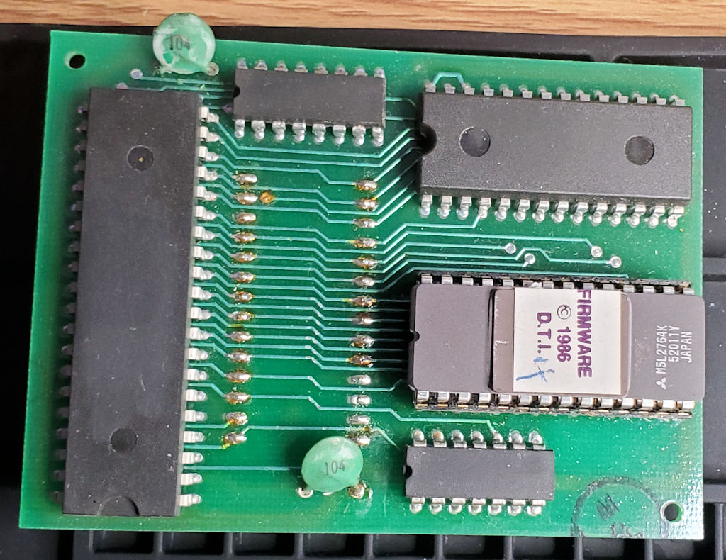
This is a closeup of the 1050 Duplicator board. Notice that Duplicating Technologies was very good at removing any identifying information regarding the IC Chips they used on the board. Other than their firmware EPROM, it is anybody’s guess on what these other chips do. I suppose DTI could have done a bit better job cleaning up the solder flux on the socket header pins. 😊 And that 104 capacitor at the top looks a bit suspect. I might have to think about replacing it if things don’t work so well after almost forty years.
Okay, enough of my rambling about what all this stuff is and on to the real task at hand which is replacing the electrolytic capacitors on the board. A relatively simple task that requires little conversation so I will just show a few pictures of it instead. This approach requires less reading on your part and less typing on mine.
With the disk drive mainboard out of the enclosure we will begin the capacitor replacement. The nine points dotted in RED are the capacitors we will replace. Note the missing capacitor point dotted has 3 thru-hole solder pads. This is to accommodate capacitors with different leg spacing distance. We will take advantage of this as my capacitors that will be replacing these old ones have the shorter leg distance. And while I’m at it I will clean up that glue glob.
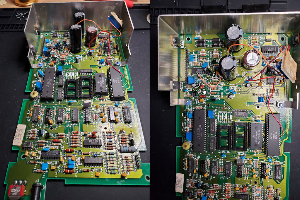
All electrolytic capacitors have been replaced. Notice that the three large capacitors originally installed are replaced with physically smaller capacitors but have the same specifications as the OEM parts.
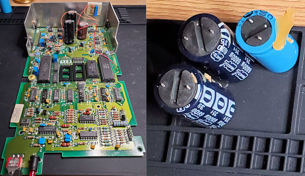
Left is the 1050 mainboard recapped and the 1050 daughter board taped back to the heatsink. Right are the three old large capacitors removed and notice the other 6800uf capacitor was beginning to bulge on the bottom as well. Would not have been long before it popped off the mainboard. Actually, removing it was very easy and I most likely did not need to use my soldering iron to loosen it up for extraction.
Next is to plug in the 1050 Duplicator board and reassemble the disk drive for testing.
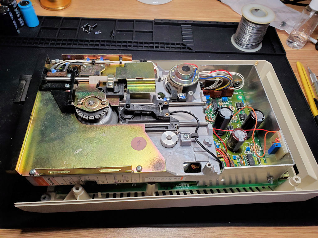
Okay, I’ve reassembled the disk drive and have everything plugged in. I’ve left the top cover off so that I can make any adjustments necessary when testing.
The initial tests went well and I’m able to boot from the drive, write to disks, format disks in both single and double density. There are moments where the drive seems to pause during I/O but does not happen all the time. It may be something with how the 1050 duplicator board handles the I/O process. It definitely tries to read and write data at higher speeds at all times. I’m not sure if there are any settings I can change on this and will need to learn more about this upgrade to determine if I have issues, or just need to configure it to work in a particular way.
All in all, this drive is functional and ready to start storing data.