
I decided to upgrade one of my Atari 800XL computers with an Ultimate 1MB FJC firmware board and a UAV. I will be using a stock fully socketed Chelco branded mainboard 800XL computer for this upgrade.
The Chelco mainboard pictured below is out of an 800XL that would not allow myself to drop out of BASIC. It had also exhibited other strange issues such as bad memory, but never in the same location during tests. As I was unable to find the problem(s) with this board, I took it to my T.A.C.O. meet up some time back to have John Hardie take a look. John subsequently could not track down the issue either, and gave it to Raymond Jett of Classic Arcade Components to see if he could find the problem. After a few hours and not getting the desired results, they were about to give up when Raymond happens to look carefully at the PBI circuit traces and found ever so slightly shorted traces across the PBI. You can see where Raymond cleaned up the circuit shorts and then used a bit of green nail polish to cover and protect the circuit trace. This solved the board issues.
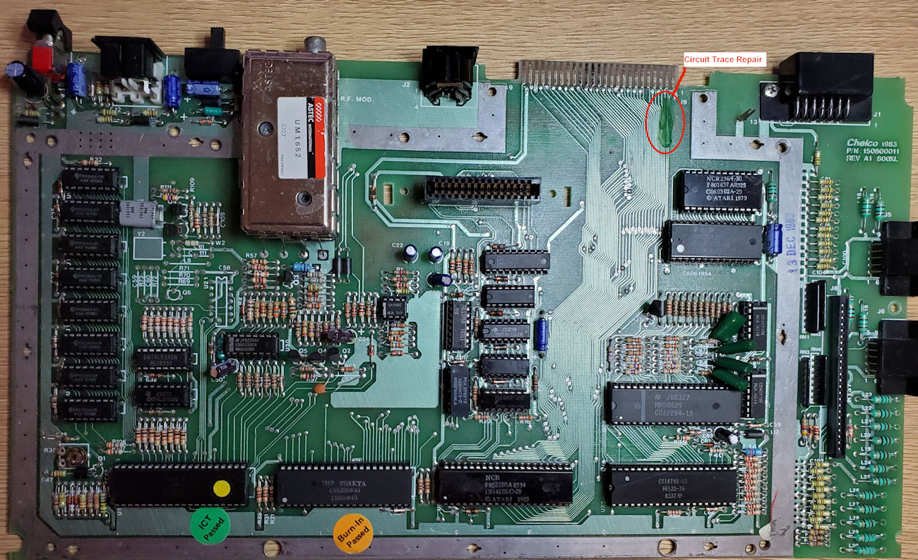
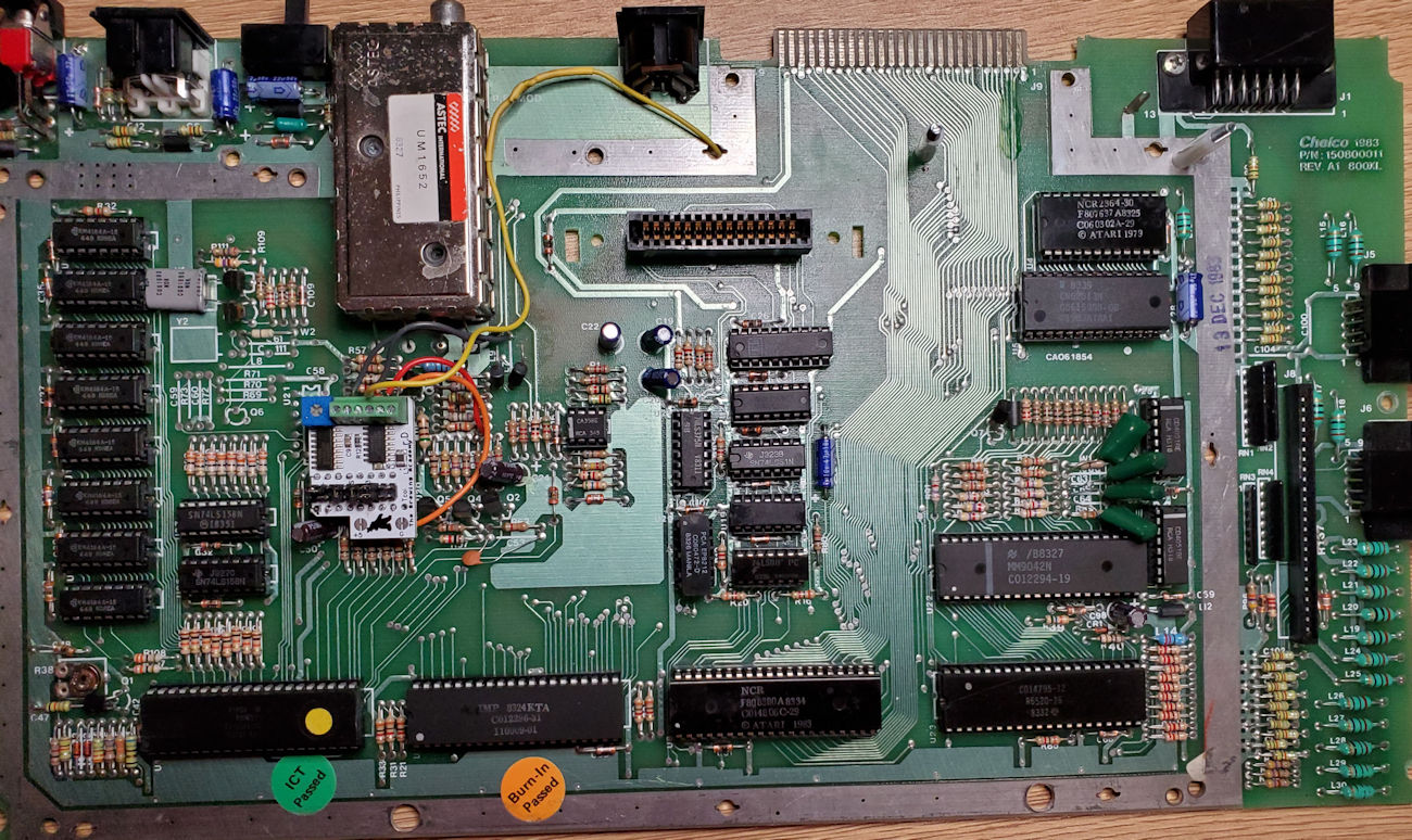
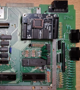
My Chelco branded 800XL mainboard prior to any modifications being made.
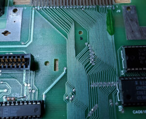
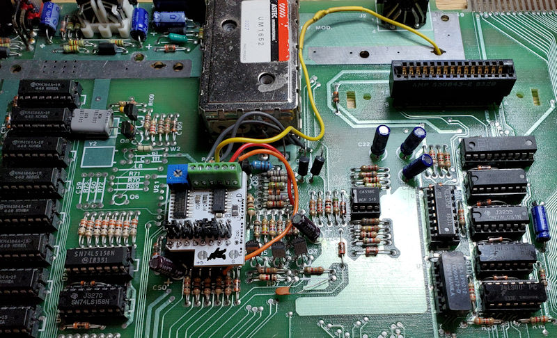
A closer view of the circuit trace repair on the mainboard
Ultimate Atari Video (UAV)
My first objective with this project is to install the UAV (Ultimate Atari Video) from the Brewing Academy. The UAV greatly enhances the video output of the Atari with a more refined composite signal and adding S-Video. For whatever reason, Atari neglected to add the Chroma signal to the output DIN, and only supplied Luma and Composite.
UAV (Ultimate Atari Video) Installation
For the UAV I won’t go into much detail of the installation procedure as that is very well documented in the provided instructions both in paper and digital form. I am basically lifting a couple of chokes and replacing the 4050 CMOS chip with the UAV circuit. This is my third UAV installation as I have already installed the UAV in a different 800XL and a 600XL. The 600XL in its original state does not include a monitor (DIN) connection or circuit components, just RF for connecting to a TV. It does have the component silkscreen and circuit traces prepped, just no components installed. I will write up on that machine later.
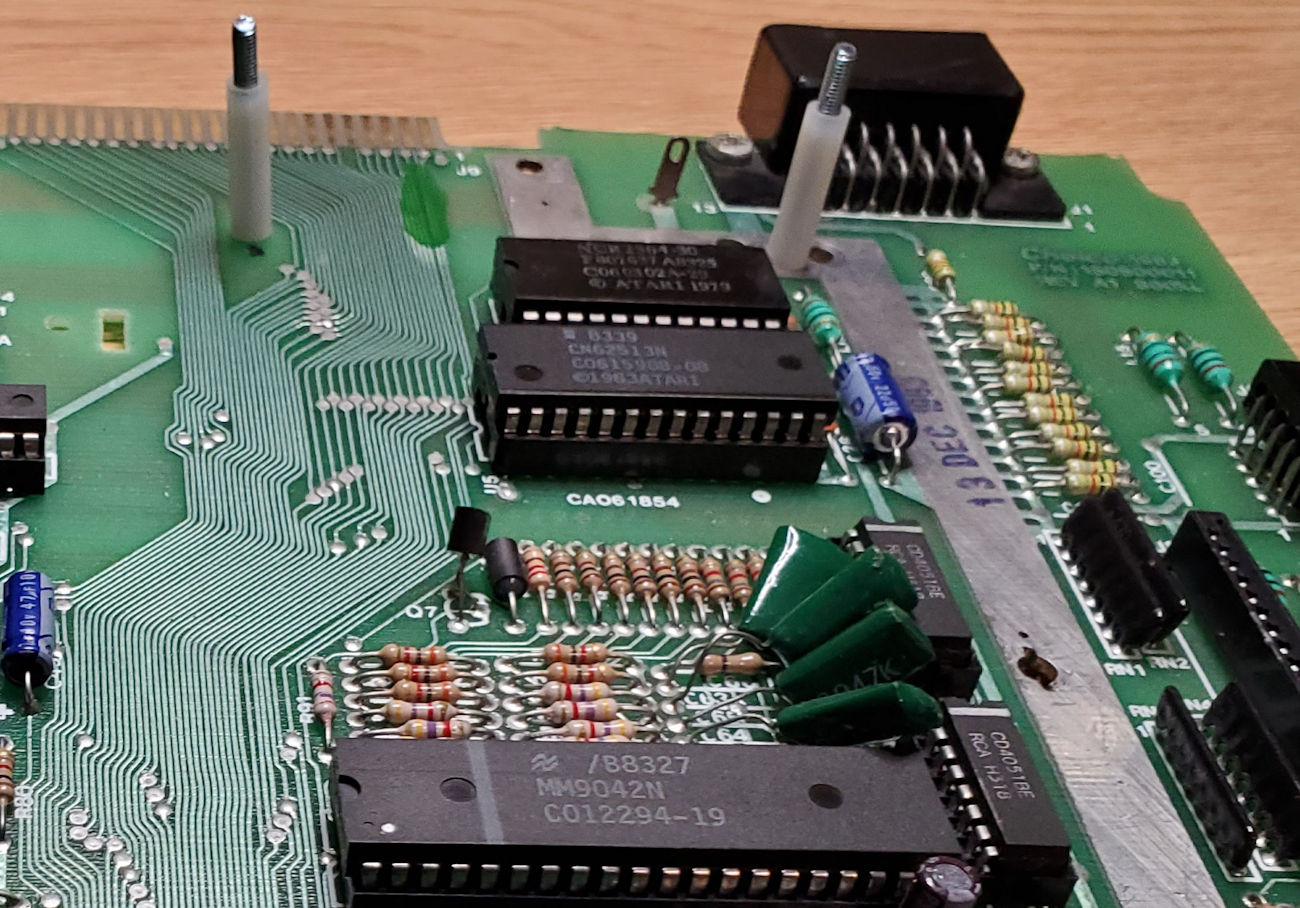
The first step of the UAV installation is to identify the connection points and prepare them accordingly. You will see in the following photo the CD4050 chip we will remove, and this is where the UAV board will plug in. Also, the two chokes will need one side lifted from the board as we will use those pads to connect a couple of wires going to the UAV. And finally, the connection for the Video In on the board as well as the ground location we will use.
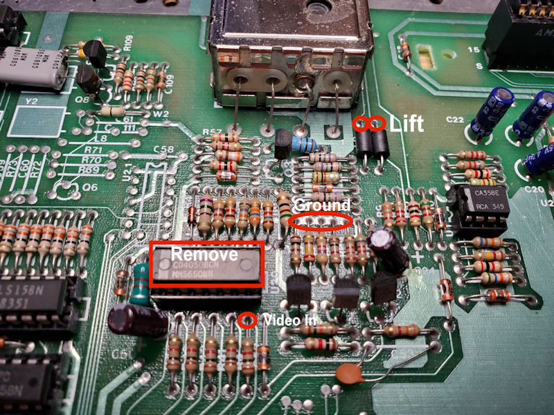
UAV connections I will use for this project.
UAV installed, notice the yellow wire? It goes thru an open hole on the board.
This is the UAV installed, and the yellow wire is the Chroma signal. The first installation of a UAV I did, had me connect the Chroma wire to pin 5 of the DIN connector on the top of the board. I found it to be a rather sloppy connection as the wire and solder used just would not adhere to the pin very well. Maybe I should have used more flux, but it just looked like a big glob of solder sitting there. On subsequent installations such as this one, I ran the chroma signal wire to the bottom of the PCB pin 5 solder pad and while the wire may be longer, it was a much cleaner and secure connection.
Full board view with the UAV installation completed.
Installing the Ultimate 1MB Memory Upgrade
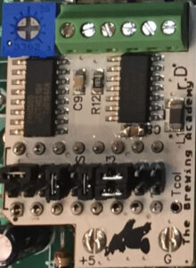
The typical Ultimate 1MB Installation Kit
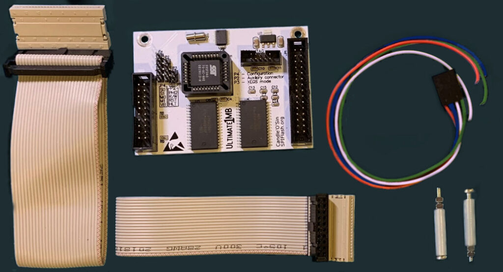
This is the Ultimate 1MB FJC (Flashjazzcat) firmware kit much like I received from Lotharek. As the picture shows, you have the Memory/OS board, a 28-pin ribbon cable for the OS socket, a 20-pin ribbon cable for the MMU socket, a 4-wire cable for connecting to the various CPU points, and 2 standoffs for mounting the memory board in the computer.
So, what is the Ultimate 1MB upgrade? As the name implies, this board expands the stock 64K RAM (required) computer up to 1MB RAM in a few different memory configurations, 1088K RAMBO, 576K CompyShop, 320K RAMBO, and stock 64K. This greatly extends the capability of the XL/XE computer that allows for running any programs requiring more than 64K memory such as AtariWriter Plus XE which requires 128K minimum. This board replaces the stock operating system (OS) ROM with a few different OS options including, XL OS 1.3, XEGS OS, Altirra OS 3.20, and Atari OS B PAL. The U1MB provides a real-time clock with the date and time compatible with the R-Time 8 cartridge format from years ago. SpartaDos X is built-in with a boot option that takes advantage of the real-time clock feature. And for my 800XL computer replaces the BASIC (rev. B) with the following programming language options that include, Atari BASIC (rev. C), Altirra BASIC, Synassembler, and Atari Assembler Editor. All of these options can be configured at boot and saved as one of four available profile defaults from a nice menu interface when you hold down the Help key upon power up. There are more advanced options for the BIOS, and this board also takes advantage of the SIDE3 cartridge, plus some PBI functions for which I have not explored.
The first step to mention is planning where you want to put this additional board in the computer. On the Atari 800XL the most common installation point is seated over top of the OS and BASIC ROM sockets. Depending on how many different modifications you do to your 800XL, it may require a different location. I will do as is the common practice of the Ultimate 1MB location.
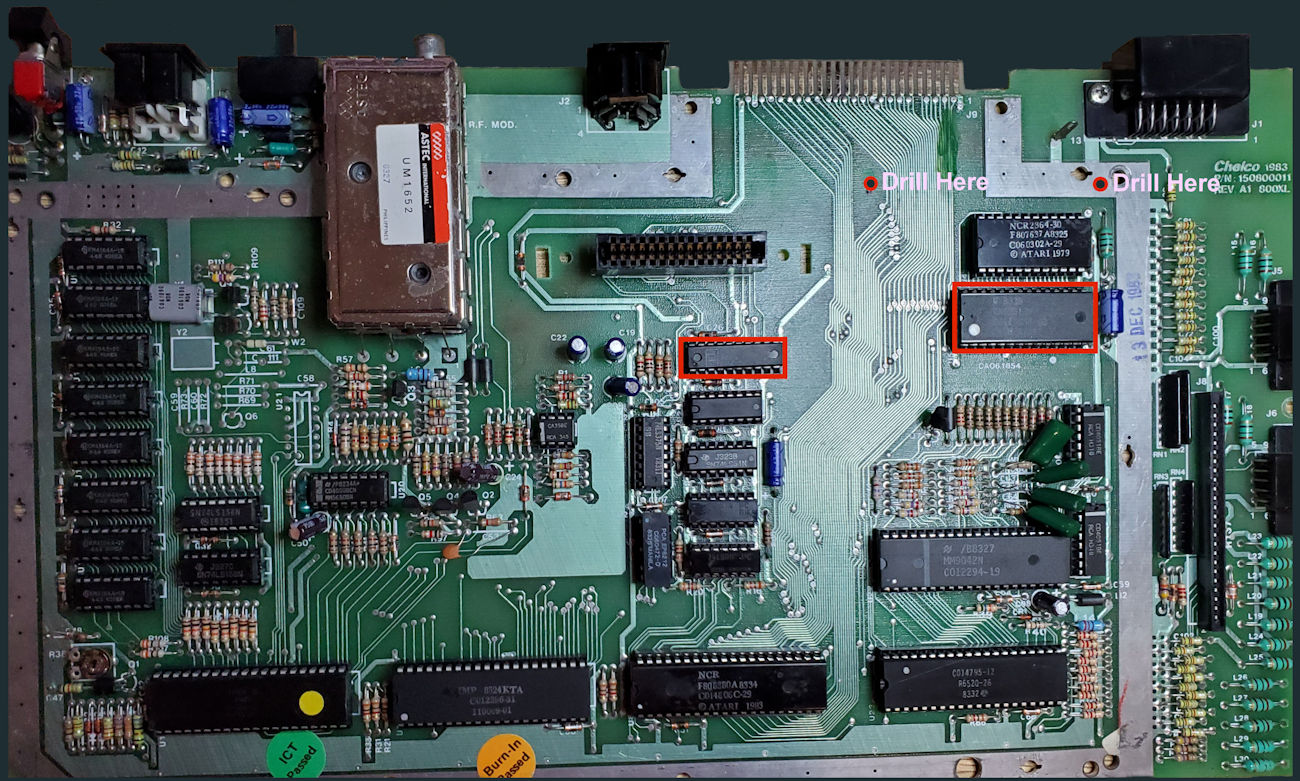
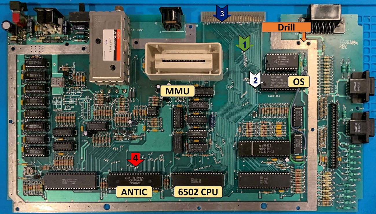
Note the locations for the U1MB board mounts, MMU and OS ROM.
Above you see the two points for which we will drill holes for the standoffs and the MMU and OS chips we will remove.
Step 1. Before I began the electronics work, I drilled the two holes that I will use for mounting the U1MB to the mainboard and did a test fit. Do be careful with drilling the holes so as to not drill through any circuit traces. Check both sides of the mainboard if you attempt to install it in a different location.
Board Mount Standoffs inserted for a test fit.
Loose fit of the Ultimate board.
After I drilled the holes, I inserted the standoffs and then put the U1MB on the standoffs just for a test fit to make sure I had the alignment correct. Note that the U1MB will extend over the existing BASIC ROM and OS ROM. There is no need to remove the BASIC ROM for this upgrade in the 800XL and it can remain in place. What is particularly nice about this upgrade is you can easily revert to your stock XL computer configuration by simply unplugging the U1MB and installing your old MMU and OS chips back in the sockets.
A bonus for this project is that the 800XL motherboard I’m using is fully socketed. This means that I I don’t need to desolder the MMU or OS chips from the board and install sockets for use of the U1MB. If your board is not socketed, it will be a bit more work, but well worth it. But for myself, it means in my next step I only have four wires to solder in place.
Thus far, of all the upgrades I have made to my Atari computers, this one is by far the simplest to do. As an example, my Wizztronics 256K RAM upgrade for one of my other XL computers required removing a resister (R32) and lifting 5 pins of the PIA chip (12 thru 16), soldering wires to each of the 5 pins that go back to the RAM upgrade board which replaces the LS158 chip. Removing all of the 4164 DRAM chips and replacing them with 41256 DRAM chips. This is where you hope your board is socketed or you will have a lot of desoldering to do. To top it off, if you want to revert to your stock XL computer it becomes a much more complex project. I state this for clarity of how much simpler the U1MB is to install even if you must desolder the MMU and OS chips. And to revert back to a stock machine is no more than unplugging the OS and MMU cables to put the old chips back in place.
Step 2. Soldering the four wires that will plug in to the U1MB is made easy as others who have installed it previously show you the solder pads to use. In the first diagram I have adjusted the wire color I’m using that will correspond to the header on the U1MB. The next diagram shows the standard 800XL mainboard again where my wire colors match up to the solder points on the board. As wire colors may change via the vendor batch shipped, it might not be the same from one installation to another. Just match your wire colors accordingly and you’ll be fine.
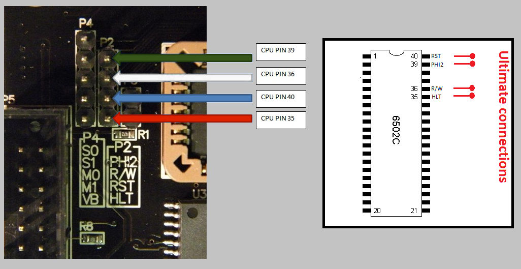
Ultimate CPU header connection diagram.
The points show where I will solder the four wires on the board.
The connection points above are not the only location that can be used, but for my installation were the most convenient.
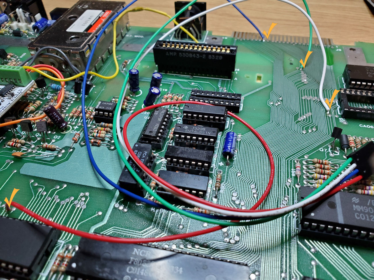
My solder work is completed!
That is all the soldering I had to do. Just those four wires as shown above. If you look at the picture, you can see I have already removed the MMU and OS chips. All that is left to do now is install the cables and board to finish this project up.
Step 3. This could be said to be the most difficult step of the project. Now I need to plug everything up which itself is not an issue. However, the cabling that comes with the U1MB is configured so that you have different options for mounting the board in the various 8-bit machines. For example, in an XE computer the typical mounting point is in the back left side of the computer by the power switch and requires a longer cable run to the MMU and OS chips. So, the installation kit is sort of a one size fits all idea in terms of the cabling provided. I could cut the ribbon cable to a shorter length for a cleaner installation, but I lack the ribbon cable connectors in my stash of parts. So, if I don’t properly disassemble the connectors (break it), I’m going to have to order replacement connectors. Or if I cut the ribbon cable too short so I can no longer reach my connection sockets, I must order more ribbon cable, and probably the connectors to go along with that. Just a bit too much of a hassle for my first-time installation. Maybe in the future I will look to clean up the cabling so that it looks factory fresh. 😊
Okay, first I lay out the cabling in a manner that lets me plug in to the sockets and route to the U1MB board. Then I plug the ribbon cables into the MMU and OS socket first as the U1MB will sit over top of the OS socket making it a bit of a challenge to plug in after I were to mount the board. Next, I loose fit the U1MB board on the standoffs and route the OS ribbon cable from underneath the board to the top connector paying attention to where pin 1 goes. Then the ribbon cable from the MMU needs to plug in to the U1MB board again paying attention to where pin 1 goes. The final part is to plug in the 4-wire header connector being mindful of color code chart I used previously for soldering to the mainboard. Really don’t want to plug any of this in backwards.
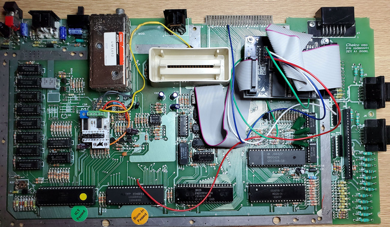
Everything installed for testing.
Before I go further, its time to test my work prior to putting the board back into the computer case. So, the above is just a loose fit of the board and cables just to make sure it works.
Well, here it goes as I flip the power switch…
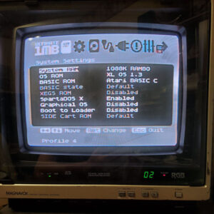
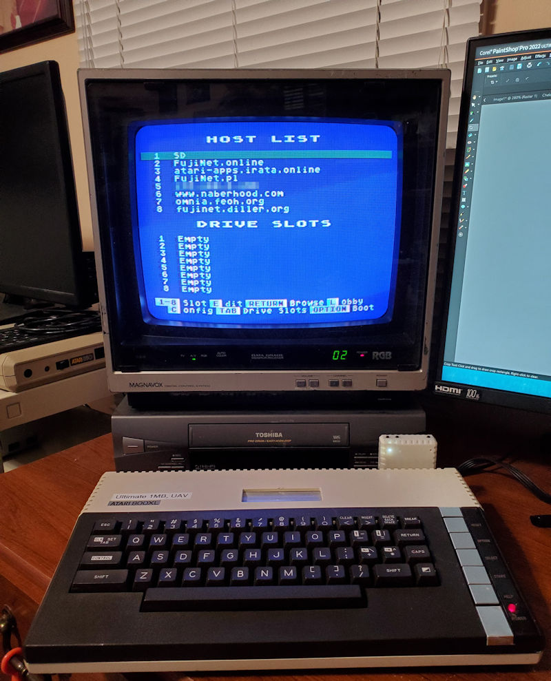
Successful Boot! Everything is wired correctly.
Success!!
Isn’t it interesting how my phone camera picks up all the Moire from the CRT screen. In person it looks a whole lot better than what you see here. The image is clear and sharp. I will have to take a picture when I connect to an LCD/LED display. Wonder how it will look on my 65-inch 4K QLED in the living room? Not that my wife will let me use it there and get in the way of her shows or anything like that?
This would be the default configuration of the U1MB which can be configured with the different OS options and ROMs as noted previously in this project documentation.
Since the loose testing was successful, it is now time to tighten things up and tidy it up as best as possible.
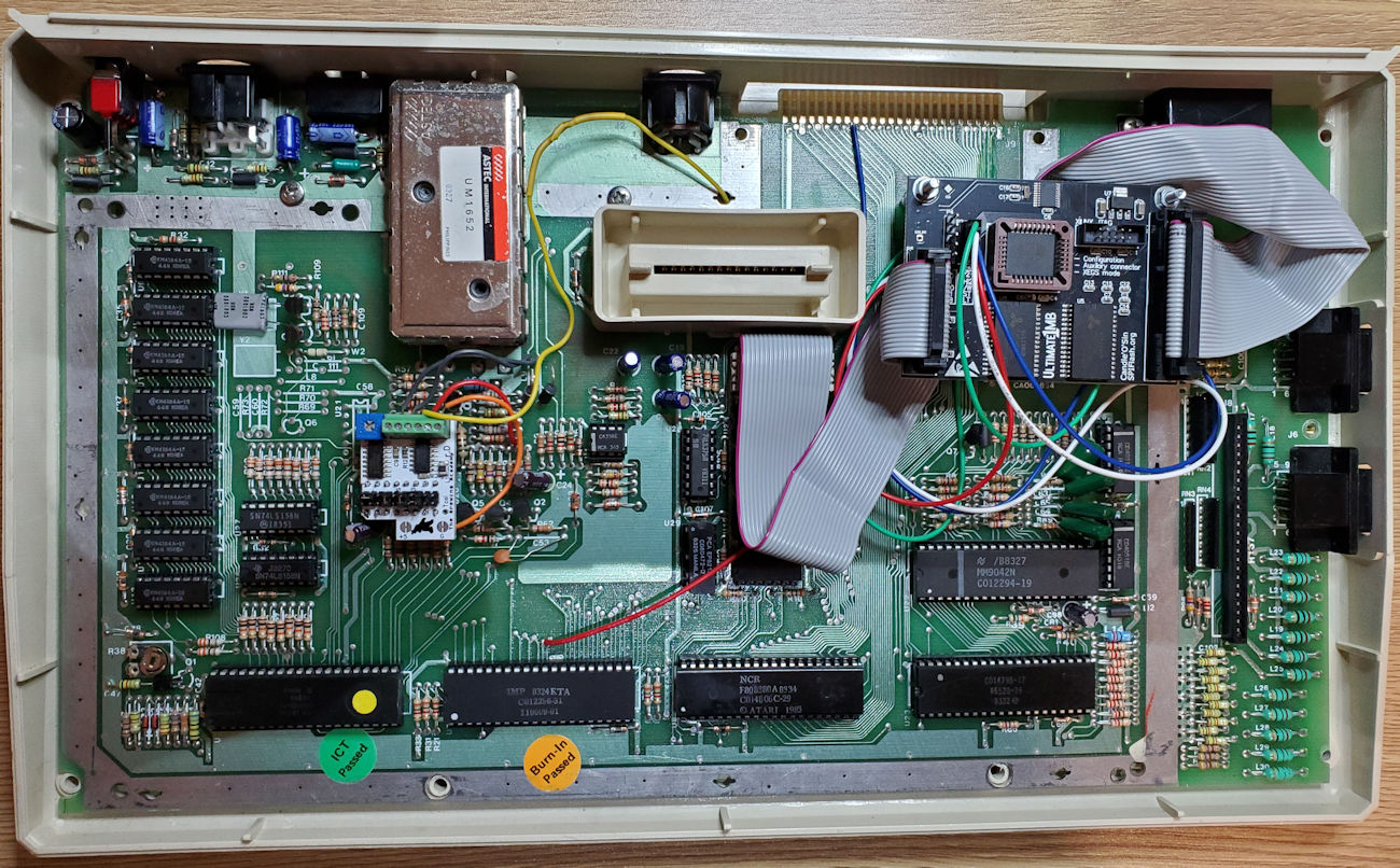
Mainboard is back in its case bottom. Time to close it up.
The finished product up and running.
And here is the completed project up and running. To recap, we have an Atari 800XL that was modified with an Ultimate Atari Video (UAV) to provide for sharper composite, and S-Video by providing both Chroma and Luma on separate signal paths.
Next is the Ultimate 1MB (U1MB) with the FJC firmware. This not only adds more memory to the computer allowing it to run any Atari 8-bit program requiring more than 64K of memory, but also adds options for different versions of BASIC, and Assembler languages. And that’s not all, you also get a real-time clock as well as Sparta Dos X built in. These two items work hand in hand allowing you to use date and time stamps on files and work well with programs looking for a clock/calendar function. The U1MB is geared for use with what is called a SIDE3 (SIDE2 is an earlier version) cartridge, which in its most basic form is a hard drive on a cartridge. It too does many different functions and is popular in Europe which is where the U1MB was designed and built.
Finally, we have a Fujinet connected to the SIO port of the computer. You could call this the New Kid on The Block of end all be all devices. The Fujinet provides wireless connectivity to the internet, mass storage for all your Atari programs and data. Incredible printer emulations that mimic a host of printers from back in the day to perfection. And as it continues to be developed, you can interact with other 8-bits such as the Apple II, Coleco Adam, and even the Commodore. Want to know where the ISS is at right now? Fujinet can show you. Would you like to display the current weather and forecast on your Atari. Yes, it can do that too.
Okay so now I will provide the cost for my project should it inspire someone else to jump on the Atari 8-bit bandwagon.
- 1 Atari 800XL (I have four so its not a fair question) that if you don’t have can be purchased via eBay from as little as $75 to more than $300. I can only say those asking big bucks, need to show me some fantastic reason why I would pay that much. But lets just assume $150 as a nominal cost.
- A Fujinet can be purchased from The Brewing Academy for $80 which includes shipping and a tip. Works in any stock Atari computer that has at least 32K of memory. Atari 400 and 600XL computers came stock with 16K and would need to be upgraded to use this.
- An Ultimate Atari Video (UAV) which is clearly optional, can be purchased from The Brewing Academy for $40 delivered. Just provides sharper video especially if you are hooking up to modern TV’s or monitors.
- The Ultimate 1MB with the FJC firmware purchased from Lotharek’s Lair in Poland for $130 that includes shipping via Polish Post Express. This amount may change a bit depending on the conversion rates of polish PLN at the time of order. I received my U1MB in just 15 days from order which is not bad.
So total to expect to pay should you need to buy an Atari 8-bit computer: $400.00
Some takeaways from this project for me.
- Since this is a hobby of which I collect Atari computers, I don’t mind modifying a unit if I have one that remains standard built. I have one 800XL which will remain stock and I keep as a show piece.
- As I do more of these modifications and repairs, my soldering skills are improving and am learning different methods to repair or maintain my 40-year-old equipment.
- This project was a great deal of fun as I just took my time with each step. So much so that I’m now breaking my own rule of maintaining one stock computer for each model as I’m upgrading my only 1200XL with all the above. Guess I need to go find another 1200XL out in the wild to put my first rule back in order.